Operation and Components of the Engine Starting System
To ensure that a gas turbine engine starts satisfactorily, two independent systems are required. In principle, means must be provided for the compressor and turbine to rotate up to a speed at which the appropriate amount of air passes into the combustion system to mix with the fuel from the injectors. Second, a means must be provided to ignite the air/fuel mixture in the combustion chamber. During engine start, the two systems must operate simultaneously. However, there must also be the possibility of turning the engine without the ignition for maintenance checks and of operating only the ignition system for restart during flight .
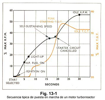
During a start-up cycle the operation of both systems is coordinated, and their operation is automatically controlled after the start of the cycle by an electrical circuit . A typical sequence of steps during startup of a turbojet engine is shown in the diagram in Figure 13-1 .
Start-up methods
The start-up procedure for all jet engines is basically the same, but can be accomplished by several methods. The type and source of power for the starting units varies according to the engine and aircraft requirements. Some use electric power, others use gas, air, or hydraulic pressure, and each has its own merits. For example, a military aircraft requires that the engine be started in the minimum amount of time and, when possible, be completely independent of external equipment. A commercial airplane, however , requires that the engine be started with minimal inconvenience to passengers and by the most economical means. Whatever system is used, reliability is of paramount importance.
The starting unit must produce a high torque and transmit it to the rotating assembly of the engine in such a way as to provide smooth acceleration from rest to the speed at which the flow of gas through the engine provides sufficient energy to the engine turbine takes care of it .
Electrical start-up
Electric starting is used in some turboprop and turbojet engines. Typically, the starter is a direct current electric motor coupled to the motor through a reduction gear and a ratchet or clutch mechanism, which automatically disengages after the motor has reached self-sustaining speed.
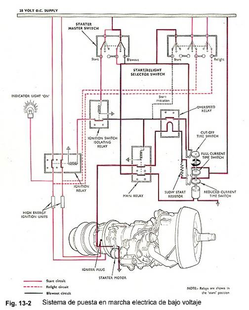
The power supply can be low or high voltage and passes through a system of relays and resistors to allow the full voltage to be applied progressively as the start-up gains speed. It also provides the energy for the operation of the ignition system. The power supply is automatically canceled when the starting load is reduced after the engine has been successfully started or when the cycle is complete. A typical electrical start-up system is shown in Figure 13-2 .
Cartridge commissioning
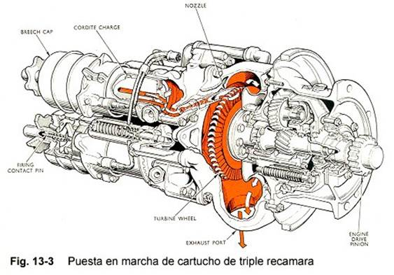
Cartridge starting is sometimes used on military engines and provides a quick, independent starting method. The starting motor is basically a small impulse-type turbine which is driven by high-velocity gases from the ignition of a cartridge. The power output from the turbine passes through a reduction gear, and an automatic shut-off mechanism to rotate the motor. An electrically triggered detonator initiates ignition of the cartridge charge. As a cordite charge provides the power supply for this type of start-up, the size of the charge required may limit the use of cartridge starts . A three-chamber cartridge startup is shown in Figure 13-3 .
Pneumatic start – ups
Pneumatic starters are used in most modern commercial and military aircraft jet engines. They have many advantages over other start-up systems, as they are comparatively light in weight while being economical and simple to operate.
An air starter motor has a turbine rotor that transmits the output power to the starter shaft connected to the engine through a reduction gear and clutch.
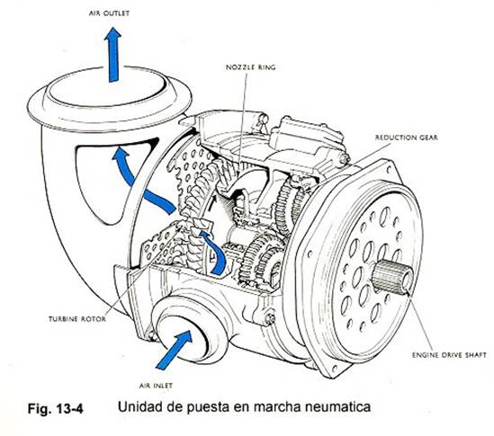
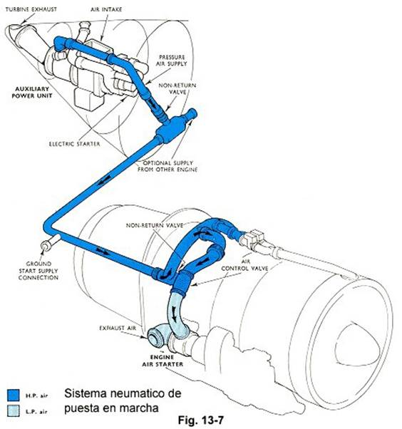
The starting turbine is rotated by pressurized air taken from an external supply on the ground, from an auxiliary power unit (APU) carried on board, or from another engine on the aircraft itself that is already running. The air supply for starting is controlled by a pressure regulator and control valve that opens when an engine start is selected and closes automatically when the starting unit reaches a predetermined speed. The clutch also automatically releases as the engine accelerates to idle rpm and cranking ceases . A typical pneumatic start-up unit is shown in Figure 13-4 .
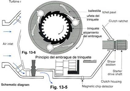
The operating principle of a pneumatic turbine start-up is described below. Air at a pressure of approximately 35 to 40 psi enters the start-up at its rear end and flows through the fixed blade passages of the turbine where its direction is altered so that it enters the turbine’s rotating blades. axial with the proper angle. The air flowing through the turbine rotates it at a speed of about 50,000 RPM, and this high speed of the turbine shaft is reduced to approximately 2,400 RPM by means of the double set of reduction gears. The output of the reduction gears is splined to the ratchet on the finger clutch and drives it clockwise.
The pawls in the clutch housing are held against the pawl teeth by a series of leaf springs (see Figure 13-6). When the pawls are engaged, the clutch housing rotates with the ratchet. When the engine starts, the housing rotates faster than the pawl, and the pawls slide on the ratchet teeth until the speed increases enough to produce enough centrifugal force to keep the pawls away from the pawl against the force of the pawls. springs.
When the engine stops, the clutch housing slows down so that centrifugal force can no longer keep the pawls out of the way, and they ride on the pawl, producing a metallic knocking noise as the turbine and compressor idle. stopping.
Pneumatic turbine startups have a shear section on the drive shaft ( see Figure 13-5 ). If the ratchet mechanism did not release, the engine would lug into gear much faster than it was designed for. When the
torque becomes high enough, the shear section will break, protecting the startup from further damage.
Air from the APU flows through a solenoid-actuated butterfly-type shut-off and regulation valve (see Figure 13-7, air control valve) controlled by the start switch in the cockpit. The valve regulator protects the startup from too high air pressure.
When the engine starts and reaches a self-sustaining speed, a centrifugal switch or RPM signal opens and de-energizes the solenoid. A spring then closes the air valve.
In this setup, there is a secondary safety feature that prevents the unloaded turbine from reaching its disintegration speed if, for any reason, the supplied air does not cut off after the engine starts. When the airflow through the fixed blades (figure 13-5 turbine nozzle ) reaches the speed of sound, the passage through them is throttled, which prevents a further increase in flow. The turbine stabilizes in an overspeed condition.
Pneumatic turbine starters have a self-contained lubrication system, with oil in the starter housing. A magnetic particle detector (Figure 13-5 magnetic chip detector ) is built into the drain plug to alert the maintenance technician of any gear damage resulting in metal flakes or chips.

Air Intrusion Starter
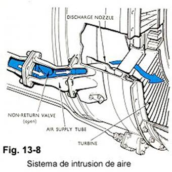
Some engines are started by a stream of low-pressure air passing through a check valve and blowing over the turbine blades. The pneumatic source is disconnected when the engine reaches a speed that allows it to accelerate without further assistance. For this type of starter, no components are required other than an air pipe, a check valve , and the nozzle that directs the air over the turbine (figure 13-8).
gas turbine starter
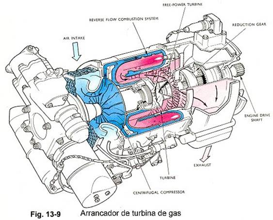
Some jet engines use a gas turbine starter that is completely self-contained. This has its own fuel and ignition system, its starting system (usually electrical or hydraulic) and its oil system. This type of starter is economical to operate and provides high power output for comparatively low weight ( Fig . 13-9).
The gas turbine starter consists of a small, compact gas turbine engine, typically equipped with a turbine driving a centrifugal compressor, a reverse flow combustion system, and a mechanically independent free power turbine. The free power turbine is connected to the main engine through a reduction gear , automatic clutch and drive shaft .
At the beginning of the start-up cycle, the gas turbine starter is rotated by its own start -up until it reaches self-sustaining speed, which is when the start – up and ignition systems automatically disconnect . Acceleration then continues to a controlled speed of approximately 60,000 rpm. At the same time that the gas turbine starter motor is accelerating, exhaust gases are directed, through guide vanes, over the free turbine to provide engine drag . major. Once the main engine reaches self-sustaining speed, a cut-off switch operates and stops the gas turbine starter. As the starter stops , the clutch automatically disengages from the drive shaft , and the main motor accelerates to idle rpm under its own power .
Ignition System and Components
All jet engines use high-energy ignition to start, and they are always equipped with a dual system. Each system has a high-energy ignition unit connected to its own igniter or spark plug, with the two igniters located in different positions in the combustion system.
Each high-energy ignition unit receives a low-voltage supply from the aircraft electrical system, controlled by the starting system electrical circuit. Electrical energy is stored in the igniter unit until, at a predetermined value, it is dissipated through the igniter as a high-voltage, high-amperage discharge.
Ignition units , also called ignition boxes or exciters, are normally sealed units and cannot be repaired at the field level. In some installations, the two exciters are incorporated into a single unit. These units are designed to give output currents that can vary according to requirements. To ensure that the engine will achieve satisfactory restart at high altitude, and sometimes for starting, a high value output power (e.g. twelve joules) is necessary. However, under certain flight conditions, such as icing or takeoff in heavy rain or snow, it may be necessary to have the ignition system running continuously to provide automatic re-ignition should a flameout occur. In this case, a low output energy value (for example three or six joules) is favorable, this results in extending the life of the igniter and the ignition box. Consequently, to satisfy all the operating conditions of the engine, it is appropriate to use a combined system that gives the high and low energy value through prior preselection as required.
An ignition unit may be supplied with direct current (DC) and operated by a switch mechanism or a pulsed transistor circuit , or supplied with alternating current (AC) and operated by a transformer.
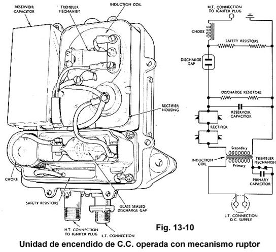
The ignition unit shown in Figure 13-10 is a typical breaker-operated DC unit. An induction coil, operated by the switching mechanism, charges the storage capacitor through a high-voltage rectifier. When the voltage across the capacitor is equal to the jump value of a sealed discharge trigger, energy is discharged through the igniter end . A self -induction coil prolongs the discharge time, and a discharge resistor is mounted to ensure that any energy stored in the capacitor is dissipated within one minute after the discharge .
system has been disconnected. The unit is equipped with a safety resistor that allows it to operate safely, even when the high voltage cable is disconnected and insulated.
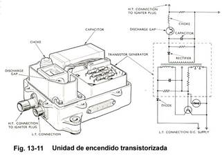
The operation of the transistorized ignition unit is similar to that of the breaker-operated DC ignition unit, except that the breaker mechanism has been replaced by a transistorized periodic interruption circuit. A typical transistorized unit is shown in Figure 13-11 ; This unit has many advantages over the breaker operated unit because it has no moving parts and offers a longer operating life . The size of the transistorized unit is smaller and its weight less than that of the breaker operated unit .
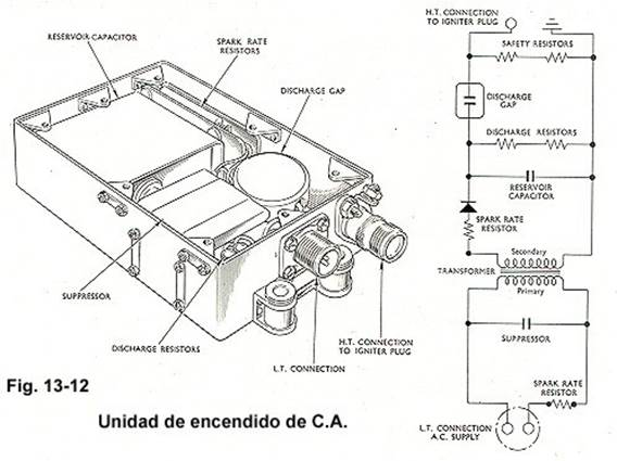
The AC – powered ignition unit, shown in Figure 13-12, receives an alternating current that passes through a rectifier transformer to charge a capacitor . When the voltage across the capacitor is equal to the jump value of a sealed discharge trigger, the capacitor discharges energy through the igniter end. Like the unit operated with a breaker mechanism , this unit also has safety and discharge resistors .
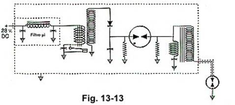
These ignition units all have , at the direct or alternating current power input , a filter to eliminate disturbing frequencies for the operation of communications systems called the P ( pi) filter. This filter consists of an inductor coil and two capacitors, one at the input and one at the output. It allows the passage of current in only one direction, and prevents the return of pulsating current. Its name derives from the resemblance of the three components in a schematic diagram to the Greek letter pi (Π).
Igniters (Spark Plugs)
The turbine engine igniters serve the same purpose as the spark plugs in a reciprocating engine: they ignite the fuel-air mixture, but their operating conditions are completely different. In a reciprocating engine, a relatively low-energy spark must jump between the electrodes of a spark plug every other turn of the crankshaft. In a turbine engine, high-energy sparks are required, but only when the engine is starting or during flight conditions when there is danger of flameout. Lighters are not prone to carbon buildup like spark plugs are, because the high – energy spark dislodges any deposits that form on the firing end .
There are a few designs of spark plugs used in all reciprocating aviation engines , but due to the difficulty in igniting the fuel – air mixture in a turbine engine , the igniters are custom made for the engine . Generally, an igniter designed for one engine will not work properly in another model.
There are two basic types of igniters : spark igniters (the most used) and incandescent igniters , which are used in some of the smaller engines .
The firing end configurations of the various types of lighters in Figure 13-14 show some of their interesting characteristics.
The tip of the surface center electrode type A lighter protrudes slightly into the combustion chamber and the spark follows the surface of the insulator between the electrodes .
The tip of the center electrode on igniter B also protrudes into the combustion chamber, but is air-cooled. Air passing around the outside of the combustion chamber flows into the lighter through the hole in its side .
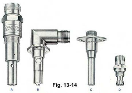
Lighter C has the central electrode hidden, and its end does not protrude into the combustion chamber. The spark does not follow the surface of the insulator , but extends beyond the tip .
The low-voltage, low-resistance electrode gap D-lighter works based on a different principle than the others. There is a semiconducting ceramic material between the center electrode and the sheath. The resistance of this semiconductor is low when it is relatively cold, but increases as it heats up. When the storage capacitor is discharged through the igniter, current initially flows to ground through the semiconductor, which becomes so hot that it glows and its resistance increases. The air space between the electrodes is ionized , and its resistance becomes less than
that of the semiconductor, so that the rest of the current is discharged through the air gap in a surge voltage in the form of a high- energy spark .
The glow igniter is only used on some small engines and is installed in such a way that some of the cooling air flowing around the outside of the combustion chamber flows into it via the glow coils. The coils are heated with current from the ignition exciter until they turn yellow-orange, and fuel from the injector, which is sprayed onto the coil, ignites . Air blowing through the coil produces a vein of flame that ignites the mixture in the combustion chamber. Incandescent lighters are especially suitable for starting in cold weather .
Maintenance Safety Requirements
Turbine engine ignition systems must be handled with extreme care because the high voltage can be fatal.
Before disconnecting the exciter cable, disconnect the power cable that powers the engine and note the time indicated in the engine maintenance handbook.This period of time, which is typically five minutes, enables the energy stored in the capacitors to be safely released into the ground via the safety resistors and bleed. Ground the center conductor to the motor as soon as the cable is taken out of the exciter to guarantee that the capacitors are fully drained.
The igniters will be removed from the engine with great care and inspected according to the instructions in the engine maintenance manual. Some lighters can be cleaned, and when working with them , be sure to follow the manufacturer’s instructions carefully . Its placement in the chambers must be carried out in a precise manner, in order to ensure that the spark plug launches the spark into the gas stream and at the same time prevents it from producing aerodynamic resistance to the flow of gas in the chamber, or therefore unless this is minimal .
Since the exciters are sealed equipment that cannot be opened for maintenance, it is important to thoroughly verify their safe mounting on the motor and make sure all electrical connections are tight and clean. There should not be any broken shield braids, and the high voltage wires should be fastened in the manner specified in the motor maintenance handbook.Certain exciters include radioactive material, which needs to be disposed of in compliance with local environmental regulations.
Leave a Reply